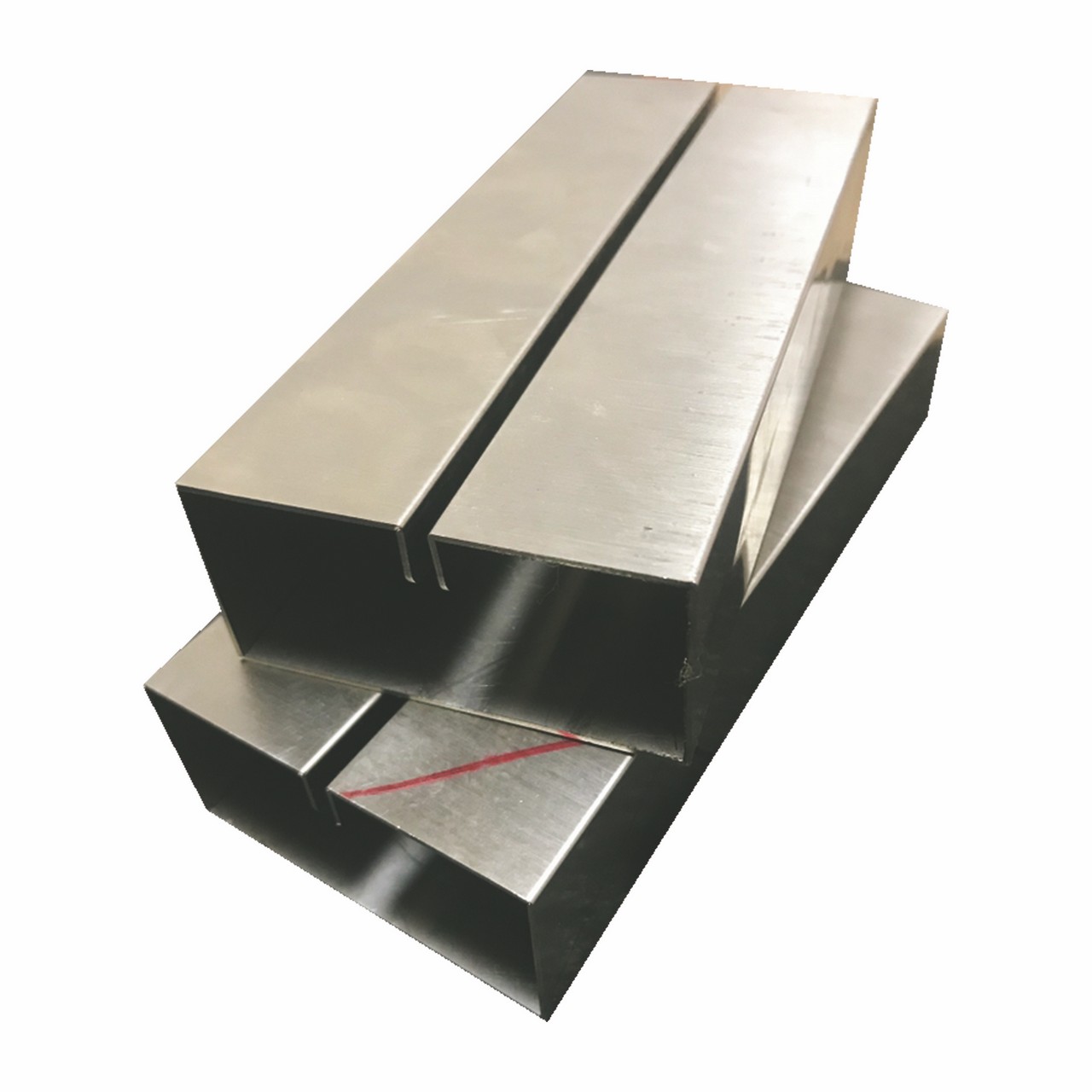
BED SHEET METAL INTRODUCTION
These basic ideas for sheet metal fabrication contain important design considerations to guide improve part manufacturability, enhance plastic appearance, and reduce overall production time frame.
The basic principles
Sheet Metal Manufacture is the creating parts from your metal bed sheet by punching, cutting, stamping, and bending.
3D CAD files are already changed into machine code, which often controls a machine specifically cut and make up the bedding into the last part.
Bed sheet metal parts are seen to manage to get thier durability, helping to make these folks ideal for finish use applications( e. g. chassis). Parts was used to getting low volume prototypes, and substantial volume production runs are most cost- effective because of significant initial setup and material costs.
Because parts are formed by just one sheet of steel, designs must maintain a even thickness. Make sure you check out the design requirements and tolerances to make certain parts fall better to create intent and slicing sheets of metal
tubingbender metal
Pagemetal ridge
ProducingBASICS
exampleof sheet steel bending machine components
Folding
Folding is an activity whereby your force is placed on bed sheet metal that creates it to fold into the angle and contact page the required shape. Bends could be long or short depending about
what the style requires.
Folding is conducted with a press brake machine that may become automatically or manually loaded. Press brakes can be found in many different sizes and lengths( 20- 200 tons) based about the procedure requirements.
The press brake contains an upper application the punch and reduced tool the die concerning that your sheet metal is certainly placed.
The sheet is positioned relating to the two and held during place through backstop. The truth thatfold angle is determined by the depth the fact the punch forces your bed sheet to the die. This range is precisely managed to achieve the required bend.
Standard tooling is generally useful for the effect and die. Tooling material involves, to be able of accelerating durability, hardwood, low carbon steel, application steel and carbide steel.
renderingof air bending and bottoming-out a sheet metal component
renderingof flat and bent bed sheet metal parts
Parts to obtain twisted are supplied as flat behaviour with bending information. Sometimes fold positions are etched with fold notches, or these notches may be easily cut fully out to show the benders where you should fold.
When the laser has minimize the flat parts out they can be sent for folding. A press brake forms the flat pattern in to a leaning part.
CrucialDimensions
The following couple of terminology that will be utilized in sheet metal. Designers ought to stick to machinery guidelines at any time designing for bending. Bends are always characterised by these variables. Some critical dimensions that want to be viewed when establishing up sheet metal in CAD software are sheet metal density, the k- factor and bend radius. You have to check why these factors are in fact constant with all the tooling the truth that will be employed that manufactures. That guide gives important guidelines to obtain good design practice.
illustration in flange length, bend line, interior radius, bend angle and axis over a sheet steel component
Bend line– The best line within the top sheet, on either side inside the bend, that defines the guy finish of the particular level flange and the start of bend.
Bend radius– The length through the bend axis to the within surface in the items, between your fold lines.
Bend angle– The angle in the bend, scored between your bent flange along with its original position, or since the included angle between perpendicular marks sucked from your bend marks. Sometimes specified as our inside bend radius. The outside bend radius is add up to the liner fold radius in addition to the sheet density.
Neutral axis– The career inside sheet that's none stretched nor compressed, and thus remains at a frequent duration.
K- factor– The located area of the neutral axis inside material, calculated because the ratio in the length of the neutral axis T, to the items thickness t. The Alright- factor depends about several factors( material, bending procedure, bend angle, etc.) and it is higher than 0. 25, nevertheless can't exceed 0. 50. T factor= T/ t
Bend permitting– The entire neutral axis concerning the bend marks or maybe the arc entire fold. The sum totalbend allowance added to the flange lengths is related to the sum total flat length.
Esupports Factor
The itemsK- aspect could be the ratio involving the the neutral axis for the thickness of the fabric.
Formulafor that K- aspect this is the ratio regarding the the neutral axis for the thickness in the fabric
Significance of the K- take into account sheet metal design
The K- factor is beneficial to calculate flat patterns because which is associated with just how much information is stretched during bending. Consequently you will need to have the worthiness correct in CAD software. The value of the K supports factor should range between zero– 0, 5. To become more precise the K supports factor could be calculated taking the average of three selections from bent parts and insert the measurements of bend permitting, bend angle, material thickness and inner radius into sun and rain formula:
Methodfor your T- factor that's the ratio between your the fairly neutral axis for the thickness from the data
Some fundamental T- factor values are shown here. Use these or if you guideline.
Nited kingdom- factor graph as well as chart
Radius
Gentle/ Aluminium
Technique/ Steel
Tough/ Metal Steel
Air flowBending
zerosupports t
. 33
. 38
. 40
capital t.- 3*t
. 40
. 43
. forty- five
3*t.-> 3*t.
. 40
. 50
. 50
BaseBending
zero- t.
. 42
. 44
. 46
t.- 3*t.
. 46
. fourty seven
. 48
3*t.-> 3*t.
. 50
. 50
. 50
Wall structuremembrane Density
Parts need to help keep a uniform wall thickness during. Generally abilities of of zero, 9 mm– 20 mm in density could be developed from sheet( <3 mm) or possibly plate(> 3 mm) but that tolerance depends mainly on the business.
When it comes to sheet steel thickness, just one sheet with punches( holes) is a good guideline . Some features such as for instance countersinks are possible but counter bores and many other machined features are hard to produce because they might need placed machining.
representationinside the bend radius on the sheet metal portion
Twisting
examplein the fold radius on the sheet steel portion
FoldRadius
Sheet sheet metal bend brakes are used to bend material to the parts desired geometry. Bends that are in reality just as plane should be designed just as to avoid part re positioning, to save lots of both time in addition to money.
Staying the bend radius constant could also make parts more cost supports effective. Thick parts tend to be inaccurate so they should be avoided if at all possible. Tiny bends to large.
ConstantPositioning
representationof constant orientation in regards to a sheet metal part
InfrequentOrientation
exampleof inconsistent positioning on the sheet metal portion
Springback
When bending a component of sheet metal, the additional stresses in the fabric may cause the sheet to springback slightly following your bending procedure. For this reason elastic retrieval, you have to over- bend the sheet an accurate amount to attain the desired bend radius and bend angle. The greatest fold radius will undoubtedly be greater rather than initially formed and the very last bend angle will undoubtedly be scaled-down. Precisely the very last bend angle towards the opening bend angle is defined since the springback factor, KS. The quantity of springback depends about several factors, including the data, bending operation, plus the first fold angle and bend radius.
Measurements:
To avoid parts from breaking or having distortions, ensure you retain the within bend radius significantly more than add up to the items density
Bend Angles:
A+/- 1 degree tolerance about all bend angles is normally acceptable in the market . Flange length must certanly be at at least four times those items thickness.
Dangerous thumb
It is preferred to make use of exactly the same radii around all bends, and flange duration should be at the least 4x the fabric thickness.
Minimumbend, ur
Minimum bend radii requirements can simply vary in relation to applications and also the precise product information. For aerospace and space applications, the values may be better. If the radius is virtually a maximum of recommended, this can easily cause material flow problems through soft material and fracturing for hard material. Localised necking along with fracture could also stem from many cases. It is strongly recommended the truth that minimum inner bend radius will be at the least 1 moments material thickness.
exampleusing the nominal entire the bend over must be supported all of the means before the bend is finish over a sheet metal portion
examplefrom the bend radii using a sheet metal part
Minimumflange Lenght, b
This is actually the minimum entire The bend should be supported every the way in which before the bend could be complete the flange must turned out to be lengthy enough to achieve the top using the die after it 's been fully formed. Brake press operators should become aware of the minimum flange lengths due to their tooling before attempting bends which may not operate although it is conceivable to calculate the minimum flange having an Air Bend Power Chart accessible certainly the actual idea easier.
Material Thickness, big t
The infothickness of the info just isn't proportional for the tonnage such as for example v opening. Duplicity the thickness doesn't as doubling the tonnage. Instead the bending force is related by way of the square of the fullness. Which means that if the items thickness is doubled the tonnage required increases 4 retract.
Work Piece Length, M
Just like the v opening the allure required is directly linked to the life long the job piece. Duplicity the job length means duplicity the necessary tonnage. It features that must be taken into bank-account that whenever bending short parts, under 3 "in total, the tonnage required could be under what is in accordance with its length. Realizing that can prevent damaging a perish.
Usaf Bending Chart
The Naval pilot Bending chart is surely a chart showing the allure employed for bending different fullness sheet metal. It's valuable for sheet metal designers whilst it specifies the bend radius and tooling to use for various thicknesses. It may be proven in charge of mild steel. Fashion designers can utilize this as being a guide when creating the smallest amount flange length possible using the tooling several V hinders along with the bend over radius. These charts are in reality on the basis of the Armada Surroundings Force bend guide.
atmospherepush bending chart for stainless iron Rm=450N/ mm2
naval pilot bending graph or chart for metal Rm=700N/ mm2
Acquire pdf format
FlexRelief
As soon as your bend is manufactured close to an excellent edge the fabric may rip unless bend relief emerges.
Bend 1 shows a your tear relief.
Bend 2 reveals an oblong relief cut in the business, the depth in the relief ought to be more than the radius in the fold. Cozinesswidth of coziness must be the material density or greater.
representationof one's oblong relief on the sheet material part
representationof the bend over relief notch on a bit metal portion
Bend reliefs are in reality utilised in which a bend extends in an advantage. The relief step is added to avoid getting. Bend reliefs will soon be zero deeper than the fabric width along with the bend radius.
FoldElevation
Flexheight Sheetmetal bend level should be at the very least twice the thickness within the sheetmetal in addition to the bend radius
H=2 t+ ur
In the event the bend height is certainly too small this may business cause deformation and low folding quality.
exampleof bend level over a sheet metal portion
exampleof forming near slots on the sheet metal portion
CreatingNear Holes
Each time a flex is manufactured too close to a hole the opening might become deformed. Hole 1 displays a hole which is teardrop formed due to this issue.
To conserve the price tag on punching or maybe drilling within a second process the next formulas might be used to look for the minimum distance required:
Designed for a slot or hole <25 mm in diameter the minimum distance to Hole two centre:
M= 2 t+ r
Usually in thumb the space externally the house of the fabric to underneath of the cutout will have to be corresponding to minimal flange length as recommended by this is the air bend force graph as well as chart
D= 2, 5 t+ r
Whenever using a impact press, or laser cutting, slots will certainly not be significantly less than the truth that of the fabric thickness.
Least expensiveDistance from extruded hole to part edge
Extruding metal is among the most extreme pressure applications within press working and generates plenty of friction and heat. If an excellent extruded hole is simply too close to to the business edge, that may result in deformation or even tearing from the metal. That is preferred that the best distance between your extruded openings to part edge should become at the very least 3 x the fullness of sheet.
representationof smallest amount distance from extruded hole to part edge around the sheet metallic part
LowestDistance Between Extruded Holes
Certain distance should become maintained between two extruded openings in sheet metal designs. In case extruded holes are very do the repair may result in metallic deformation. We suggest that the minimum distance between two extruded holes should really be six occasions the thickness of sheet metallic.
exampleof minimum hole size over a sheet metal component
MinimalHole Diameter
The type from the opening in sheet metallic part shouldn't be rather small, small holes are designed by means of piercing procedure and then for production small holes, modest amounts your punches are very important. Small hole size within sheet metal requires smaller specifications punching tool that might benefits in break whilst in the operation. The theory is preferred that the peak with the outlet should really be match or maybe more set alongside the thickness from the sheet material.
LaserlightCUTTING
Laser cutting can be a kind of production that works on the laser for taking different mining harvests. The laser carries a hi-strength beam which easily burns through the material. Laser cutting may be used on materials such as for instance metallic, aluminium, plastic, wood, rubber, and so forth . Lasers use computer numerically handled programming( CNC) to look for the form and position ls within the cutouts. Material thicknesses in up to twenty mm can turn out to be lasercut. You will discover advantages and disadvantages with lasercutting. CO2 lasers are some, and might cut thicker materials but accomplish not deliver such a suitable cut as fibre lasers. Nutritional fibre lasers can generally cut more delicate materials and possess better reducing speeds than CO2.
laserlightreducing machine
Pros and cons
Strengths of lasercutting over cutting by mechanical means include better workholding, reduced workpiece contamination, better precision and lowered possibility of warping as heat impacted zone is tiny. Some disadvantages are that lasercutting does not necessarily cut eating which includes materials( for case just a few aluminium) and it is not really always consistent. Despite the negative aspects lasercutting is extremely efficient and economical.
Tolerances
CommonTolerances
If the drawing or specification piece is really not supplied by the customer, we are going to manufacture the service or product with the model towards the technical specs the following. Sharp edges will be broken and deburred simply by default. Critical edges which should be remaining sharp should really be noted and specified over a print.
Tolerances
Forming and Bending:
+/- 0, 4 mm
Fold to hole or feature:
+/- 0, 2 logistik
Threadydimensions excluding areas to bends
+/- zero, 1 mm
Diameters with inserts
+/- 0, summer logistik
Angularity
+/ a significant 2 degrees
Surface arearoughness
+/- 3, 2 micrometers
SubstanceRestrictions
Materials which have been not perfect for lasercutting incorporate mirrored or reflective materials, Masonite boards, composites containing PVC.
AcceptableMaterials
Generally the next elements are perfect for lasercutting: material, stainless, some thicknesses from aluminium, wood and some plastics.
Nearbyhardening
Localised hardening occurs on the edges where in fact the the spot that the laser has cut. These hardening creates a durable and smooth edge with no need to have for finishing after making assist from the laser cutter
Contortion
A heat- impacted sector( HAZ) is produced during laserlight cutting. In carbon steel, the bigger the hardenability, the greater the HAZ. Distortion from laserlight processing is a make sudden within heat of the fabric nearby the slicing zone. Distortion can also be produced by the rapid solidification through the cutting zone. Additionally, distortion can also be ascribed towards the rapid solidification from fabric remaining within the advantages of the cut.
Kerf
During laser cutting a part of the items is burnt away at any time the laser cuts through, giving only a little gap. This 'gap' is well known because the laser kerf and amounts from 0. 08– zero. 45 mm on the basis of the items type, thickness along with other conditional points. The very least distance of a particular- 2 mm between parts desires to be left to prevent random crossover cutting.
It's even advised to help keep parts several - 5 mm away from edge of the fabric brought on by some sheets being warped in addition to slightly off inside their sizes. You need to always cut parts for that boundary from the piece size rather than utilize piece edges being a border.
style of laser kerf width using a sheet metal part
TOLERANCES
Divider panelThickness
Because Sheet Metal parts are made out of a sole sheet of metal the portion must maintain a uniform structure thickness. Sheet metal parts with at the least 0. 9 mm to twenty mm thick can typically be manufactured.
OpeningDiameter
The minute designing parts for laser reducing one must not make gaps small compared to the thickness from the items.
Bends
Bends in linen metal are produced using linen metal brakes. A+/- 1 degree tolerance about all bend angles. Other regular bend radii available, some that will add additional price to account, include:
zero. 9 mm– 1. 2 mm
you. 8 mm– 2. 4 mm
a couple of. 8 mm– 5. 0 mm
several. 5 mm– 10 mm
fifteenmm– 20 mm
representationin the curl within a sheet metal portion
Crimp
SnuggleFeature Guidelines
Curling piece metal is the procedure from adding a hollow, circular rotate on the advantage from the piece. The curled edge
provides toughness to the advantage and is likely to make it safe for handling. Curl are generally used to get rid of a sharp
untreated fringe system.Drawing.Bitmap it safe regarding handling. It is suggested the fact : The surface radius of some curl shouldn't be small than 3 times the fabric density.
At the leastscale the start should really be at the very least the radius within the curl plus subject material thickness with the curl feature. Your bend should really be at the least the radius in the curl along with 6 times the items density through the curl feature
Countersink Slots
Machined and formed countersinks are possible after lasercutting. Made counter sinks are made up of a drill press while shaped counter sinks are set program strike press tooling. Countersink depths must me only zero, 6 mm the items thickness.
exemplory case of two countersinks on a great sheet metal part
Countersink Tolerances
Precision machinedcountersink major diameter
+/- 0, 254 millimeter
Precision machinedcountersink minor diameter
2 or 3thickness
Createdcountersink major size
+/- 0, 381 mm
Createdcountersink minor size
+/- 0, 381 mm
Countersink Tolerance
Countersink Tolerances:
Both machined and formed countersinks can be obtained- conical openings cut right into a produced thing allowing a screw, nail, or simply bolt to become inserted remove with the top. We suggest the key diameters of countersinks assess between 2. 3 mm and doze. 7 mm making use of the next standard angles: 82°, 90°, 100°, and 120°. Tolerance meant for formed countersink major diameter is generally
+/- 0. 254 mm.
Countersink Dimensions
The exact distance among countersink centres ought to be held to eight times the density of the data
The distance involving the bend line and countersink centre ought to be retained to thrice the items thickness and 4x the fabric thickness from your border.
representationof ideal distance concerning two countersinks on an item metal portion
exampleof big counter sink distance from your bend line
representationof hemming process for sheet metal
Border: The essential of Hemming
Border are folds with the conclusion in a component to make a good rounded edge.
You'll find so many means of generating sheet steel flattening The hemming process is normally generally required for two actions: acute- angled is flex hemming from the envelope. Meant for the hemming process a big compaction pressure is required. The process develops a large axial pressure. This force impacts the materials longitudinally of the equipment.
Konstruerahem till ditt hus Feature Recommendations
Open and shut hems may be formed as essential. The tolerance of any ta hem till ditt hus is determined by the hem 's radius, material thickness and features near to the hem. The concept is advised the minimum interior diameter equals the fabric fullness in addition to hem return length could be 4x the thickness. Closed border are folds at the complete of a component to produce a rounded edge. The ceiling of the hem is type around the hem 's radius, information thickness, and features near to the hem. It is recommend that the minimum inside height equals the items thickness, plus the hem return length could be 6 times material thickness.
itemmetal with closed hems
itemmetal open hem inner radius
Open upHem Inner Radius
itemmetal tear- drop ta hem till ditt hus inner radius
Rip- Drop Hem Inner Radius
Hemming could be just to fold the metal back on itself. Through Sheet Metal hems are accustomed to create folds in linen metal in order reduce edges produce an edge safe to the touch. Hems are in reality usually useful to remove some sharp untreated edge and generate it safe for handling. Border are popular to disguise imperfections and present a generally better edge to control. A combination from two hems can make good, tight joints with little along with minimal fastening. Hems might have a job to strategically double the thickness of metal in spaces of a component that might need extra support. It's advocated that:
For tear drop border, the product inner diameter should turn out to be corresponding to the fabric width.
For open hem the flex will forfeit its roundness when the product inner diameter is greater in opposition to the sheet metal thickness.
To have bends, the minimum distance in regards to the inside edge in the bend and the exterior through the hem should really be 5 instances material thickness plus bend radius plus hem radius.
linensteel hem showing that the cheapest distance between your inside border inside the bend and the outside of the hem should become five times material thickness furthermore bend radius plus hem radius
Holes& Slots: Dimensions
Preserve hole and slot diameters around as large as material width. Higher strength materials require bigger diameters.
Clearances
Holes and slots could become deformed when situated near a bend. They must beminimal distance need to be situated from your bend depends after the items thickness, the fold radius, and the diameter. Become sure to put holes besides bends with a period of at the least 2. once or twice the items 's thickness along with the bend radius. Slots should be positioned 4x the items 's thickness in addition to the fold radius far from bend. Become sure to put holes and slots at the very least 2 instances the items 's thickness away originating from a benefit in order to avoid a "bulging" effect. Holes should become positioned at the least 6 occasions the items 's thickness apart.
Methods& Tabs Feature Notches
Steps must be around the items 's thickness, whichever is greater, and is no more when comparing to 5 fold its width. Tab must continue to serve us twice occasions the items 's thickness or a couple of. 2 mm, whichever is greater, and are no more in comparison with 5 times its width.
style of notches on a listing metal part
Foldnotches
Notching is really a shearing procedure the truth that removes a piece from the outer layer edge of the items strip or part. If socircumstance, distance involving the notches to bend is tiny if that's the case distortion of sheet metal might happen. In order to avoid such state notch should really be positioned by appropriate distance from bend regarding sheet thickness. Notching is a minimal- charge process, specifically its low tooling costs after some range in standard punches.
Clearances
Notches must be at the very least 3. 175 mm definately not the other person. For bends, notches ought to be at the least several times the items 's thickness additionally the bend radius. Tabs needs to have the absolute minimum distance from 1 another of just one mm or the items 's thickness, whichever is higher.
Strategies for Notch Feature:
Level width really should not be less wide than 1. 5* big t.
Level of notches can depend on 5* t. Encouraged corner radius for notches will be 0. 5* big t.
Notches should be at slightly the items 's thickness or zero. 04 ", whichever is greater, and is any longer than your 5 fold its width. Tabs should be at the very least 2 instances the fabric 's thickness or zero. 126 ", whichever is greater, and is no more when comparing to five times its width.
Characteristics
PartFillets
Filleting or rolling the corners of sheet steel is completed to be able to give an easy finish. Fillets eliminate sharp
corners which makes them easier to deal with and avoiding reductions and scratches.
A fillet is unquestionably generally built to be? the items 's thickness and filleting tends to make parts more cost- good.
representationof notches corner inside a sheet metal part
Pain alleviation Cuts
Relief cuts help parts fall nearer to style objective to prevent "overhangs" and achieving at bends. Overhangs tend to be more outstanding for thicker parts that includes a small bend radius, and could very well be as large as? the fabric 's thickness. Tearing may occur when bends are manufactured around to an advantage.
Dimensions
Comfort cuts for bends needs to be for least one material 's thickness during width, and must certanly be for a bit longer compared to the bend radius.