COMPUTER NUMERICAL CONTROL machining is the term commonly utilized in manufacturing plus commercial applications. Yet specifically what is definitely CNC? And precisely what is a COMPUTER NUMERICAL CONTROL machine?
Medium_shutterstock_1504792880-min. digital - a min before
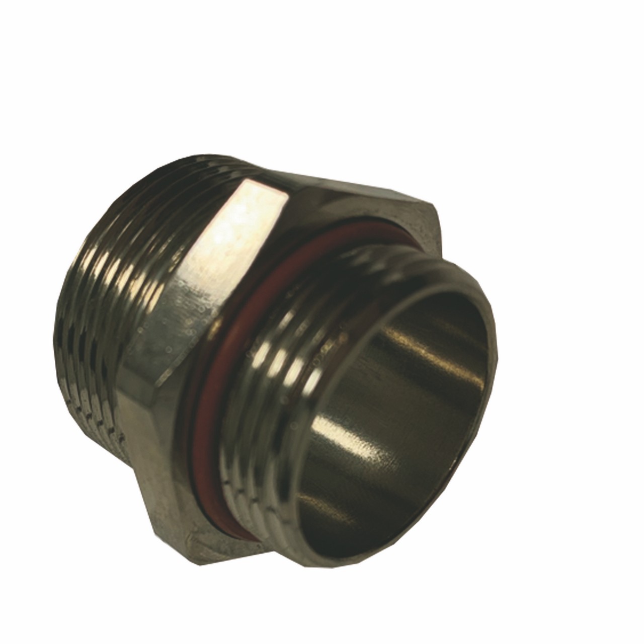
A COMPUTER NUMERICAL CONTROL machine performing milling functions on a new workpiece.
Precisely what is COMPUTER NUMERICAL CONTROL Machining?
CNC information: The term COMPUTER NUMERICAL CONTROL stands for 'computer numerical control', and even the CNC engineering definition is that is a subtractive manufacturing process of which typically employs electronic controls and equipment tools to take out layers of cloth from a inventory piece—known as typically the blank or workpiece—and produces a custom-designed part. This method is suited to an array of materials, including precious metals, plastics, wood, goblet, foam, and mêlé, and finds app in many different industries, these kinds of as large COMPUTER NUMERICAL CONTROL machining, machining regarding parts and representative models for telecommunications, and even CNC machining jetstream parts, which demand tighter tolerances as compared to other industries. Be aware there is a new difference between your COMPUTER NUMERICAL CONTROL machining definition and even the CNC equipment definition—one is a new process and typically the other can be a equipment. A CNC equipment (sometimes incorrectly called to as a new C and G machine) is a new programmable machine of which is capable regarding autonomously performing the particular procedures of COMPUTER NUMERICAL CONTROL machining.
CNC engineering like a manufacturing procedure and service will be available worldwide. A person can readily discover CNC machining solutions in Europe, along with Asia, North The united states, and elsewhere close to the globe.
Subtractive manufacturing processes, like CNC machining, in many cases are presented in comparison to additive production processes, like THREE DIMENSIONAL printing, or conformative manufacturing processes, this kind of as liquid shot molding. While subtractive processes remove levels of material through the workpiece in order to produce custom designs and designs, ingredient processes assemble levels of fabric in order to produce the preferred form and conformative processes deform plus displace stock materials in to the desired form. The automated character of CNC engineering allows the manufacturing of high accuracy and high precision, simple parts plus cost-effectiveness when satisfying one-off and medium-volume production runs. On the other hand, while CNC engineering demonstrates certain positive aspects over other developing processes, the education of complexity and even intricacy attainable intended for part design plus the cost-effectiveness of creating complex parts is definitely restricted.
While each and every type of making process has their advantages and cons, this article is targeted on the CNC engineering process, outlining the fundamentals of the procedure, as well as the various parts and tooling associated with the CNC device. Additionally, this short article is exploring various mechanical COMPUTER NUMERICAL CONTROL machining procedures plus presents alternatives in order to the CNC engineering process.
At the glance, information will certainly cover:
Overview associated with CNC Machining Procedure
Forms of CNC Engineering Procedures
CNC Engineering Equipment and Parts
CNC Machining Components
CNC Size Factors
Alternatives to Making use of a CNC Device
History of COMPUTER NUMERICAL CONTROL Machining
Are a person between jobs right this moment or an company looking to employ? We've got a person covered with each of our in-depth collections involving resources for professional job seekers and even employers looking to be able to fill roles. In the event that you have the open position, an individual can also complete out our kind for a possiblity to have it highlighted inside the Thomas Regular monthly Update newsletter.
Guide of CNC Engineering Process
Evolving by the numerical handle (NC) machining method which utilized smacked tape cards, COMPUTER NUMERICAL CONTROL machining is some sort of manufacturing process which in turn utilizes computerized handles to control and shape machine and reducing tools to condition stock material—e. grams., metal, plastic, wooden, foam, composite, and so on. —into custom components and styles. Whilst the CNC engineering process offers numerous abilities and functions, the fundamental rules in the process stay largely the similar throughout every one of them. The particular basic CNC engineering process includes the next stages:
Designing the particular CAD model
Renovating the CAD data file to a COMPUTER NUMERICAL CONTROL method
Preparing typically the CNC machine
Running the machining functioning
CAD Model Design and style
The CNC engineering process commences having the creation involving a 2D vector or 3D sound part CAD design and style either in-house or even by a CAD/CAM design service business. Computer-aided design (CAD) software allows developers and manufacturers in order to produce a type or rendering associated with their parts in addition to products together with the essential technical specifications, this kind of as dimensions in addition to geometries, for generating the part or perhaps product.
Designs to get Cnc-machined parts happen to be restricted by typically the functions (or inabilities) of the COMPUTER NUMERICAL CONTROL machine and pedaling. For example, nearly all CNC machine pedaling is cylindrical thus the part geometries possible from your COMPUTER NUMERICAL CONTROL machining process happen to be limited for the reason that pedaling creates curved area sections. In supplement, the properties on the material being precision machined, tooling design, in addition to workholding features in the machine further prohibit the design opportunities, like the minimum portion thicknesses, maximum portion size, and introduction and complexity regarding internal cavities in addition to features.
Once the particular CAD design is usually completed, the artist exports it in order to a CNC-compatible record format, such like STEP or IGES.
CNC Machining Tolerances Platforms
When indicating parts to some sort of machine shop, they have important to include things like any necessary tolerances. Though CNC equipment are incredibly accurate, that they still leave quite a few slight variation involving duplicates of typically the same part, commonly around + or perhaps -. 005 throughout (. 127 mm), which is around twice the thickness of any human curly hair. To reduce charges, buyers should just specify tolerances inside areas of the particular business that may need to end up being especially accurate since they should come directly into contact with other areas. While there are usually standard tolerances with regard to different amounts of engineering (as demonstrated within the tables below), not all tolerances are equal. In case, for instance, the part absolutely can not be larger than the particular measurement, it may have a specific tolerance of +0. 0/-0. 5 to exhibit it can become slightly smaller, yet no larger within that area.
Desk 1: Linear Tolerances in CNC Architectural
Dimension Range (mm)
Fine (F)
+/-
Medium (M)
+/-
Coarse (C)
+/-
Very Coarse (V) +/-
. 5-3
. 05
. 1
. 2
--
3-6
. 05
. one
. 3
. 5
6-30
. 1
. 2
. your five
1. 0
30-120
. 15
. 3
. 6
1. 5
120-400
. 2
. 5
1 ) 2
2. your five
400-1000
. 3
. 6
2. 0
some. 0
1000-2000
. your five
1. 2
several. 0
6. actually zero
2000-4000
--
2 . not 0
4. actually zero
8. 0
Stand 2: Angle Tolerances in CNC Anatomist
Dimension Range (mm)
Fine (F)
+/-
Medium (M)
+/-
Coarse (C)
+/-
Very Coarse (V) +/-
0-10
1o
1o
1o 30’
3o
10-50
zero o 30’
zero o 30’
1o
2o
50-120
zero o 20’
zero o 20’
zero o 30’
1o
120-400
0 um 10’
0 um 10’
0 um 15’
0 um 30’
400
zero o 5’
zero o 5’
zero o 10’
zero o 20’
Stand 3: Radius and even Chamfer Tolerances within CNC Machining
Dimensions Range (mm)
Good (F)
+/-
Moderate (M)
+/-
Rough (C)
+/-
Really Coarse (V) +/-
. 5-3
. 2
. two
. 4
. 4
3-6
. 5
. 5
one
1
6
one
1
2
two
CAD File Transformation
The formatted CAD design file operates through a system, typically computer-aided production (CAM) software, in order to extract the component geometry and produces the digital development code that will manage the CNC device and manipulate the particular tooling to create the particular custom-designed part.
COMPUTER NUMERICAL CONTROL machines used a number of programming languages, which includes G-code and M-code. The most recognized of the COMPUTER NUMERICAL CONTROL programming languages, common or geometric program code, known as G-code, regulates when, where, plus how the equipment equipment move—e. g., whenever to turn upon or off, exactly how fast to journey to a specific location, what pathways to consider, etc. —across the workpiece. Assorted function code, known to as M-code, controls the additional functions of the particular machine, such while automating the treatment and replacing typically the machine cover at the beginning and conclusion regarding production, respectively.
After the CNC program is definitely generated, the user loads it for the CNC machine.
Equipment Setup
Before typically the operator runs the particular CNC program, these people must prepare the particular CNC machine with regard to operation. These arrangements include affixing the particular workpiece straight into the particular machine, onto equipment spindles, or in to machine vises or even similar workholding equipment, and attaching the mandatory tooling, such while drill bits and even ending mills, in order to the proper device components.
After the equipment is fully collection up, the agent can run typically the CNC program.
Engineering Operation Execution
Typically the CNC program is going to act as guidance for the COMPUTER NUMERICAL CONTROL machine; it submits machine commands dictating the tooling’s measures and movements for the machine’s integrated laptop or computer, which operates together with manipulates the equipment tooling. Initiating typically the program prompts typically the CNC machine to be able to get started the COMPUTER NUMERICAL CONTROL machining process, together with the program tutorials the machine through the process since it executes the essential machine functions to generate a custom-designed part or even product.
CNC engineering processes can end up being performed in-house—if the particular company invests inside obtaining and sustaining their particular CNC equipment—or out-sourced to devoted CNC machining services providers.
Varieties of COMPUTER NUMERICAL CONTROL Machining Functions
COMPUTER NUMERICAL CONTROL machining is actually a producing process suited to some sort of wide variety involving industries, including car, aerospace, construction, together with agriculture, and ready to produce some sort of product selection, such like automobile frames, operative equipment, airplane applications, gears, and side and garden resources. The process involves several different computer-controlled machining operations—including physical, chemical, electrical, together with thermal processes—which take away the necessary product from the workpiece to produce a new custom-designed part or even product. While chemical substance, electrical, and energy machining processes are usually covered inside a later on section, it is exploring some of the most typical mechanical CNC engineering procedures including:
Heading
Milling
Turni
Going is a engineering process which uses multi-point drill parts to produce cylindrical holes in the workpiece. In COMPUTER NUMERICAL CONTROL drilling, typically the CNC machine nourishes the rotating exercise bit perpendicularly to the plane of the workpiece’s surface, which produces vertically-aligned holes with diameters equal to the diameter of the drill bit applied for the going operation. Yet , slanted drilling functions can be performed with the use of particular machine configurations and workholding devices. Detailed features of the drilling process include counterboring, countersinking, reaming, and tapping.
COMPUTER NUMERICAL CONTROL Milling
Milling is a machining process which employs spinning multi-point cutting tools to remove stuff from the workpiece. In CNC milling, the CNC machine typically feeds the workpiece to the cutting tool in the same course as the reducing tool’s rotation, whilst in manual milling the appliance feeds the workpiece in the opposite direction to the cutting tool’s rotation. Operational features of the milling process include face milling—cutting shallow, level surfaces and flat-bottomed cavities to the workpiece—and peripheral milling—cutting serious cavities, such as slots and posts, into the workpiece.
CNC Turning
COMPUTER NUMERICAL CONTROL Turning and Variable Spindle Machining
COMPUTER NUMERICAL CONTROL Turning and Multi-Spindle Machining
Image Credit rating: Buell Automatics
Transforming is a engineering process which uses single-point cutting tools to remove stuff from the spinning workpiece. In COMPUTER NUMERICAL CONTROL turning, the machine—typically a CNC lathe machine—feeds the reducing tool in a linear motion alongside the surface of the rotating workpiece, removing material around the circumference before the desired diameter is achieved, to produce cylindrical parts with external and interior features, such as slots, tapers, and threads. Operational features of the transforming process include dull, facing, grooving, and thread cutting. Whenever it comes down to a COMPUTER NUMERICAL CONTROL mill versus lathe, milling, using its revolving cutting tools, works better for more complex parts. Nevertheless, lathes, with revolving workpieces and fixed cutting tools, work best with regards to Smaller, more accurate creation of round parts.
Desk 1 – Features of Common COMPUTER NUMERICAL CONTROL Machining Operations
Notice: Some CNC engineering procedure information provided courtesy of Metallic Craft.
Machining Procedure
Features
Drilling
Uses rotating multi-point exercise parts
Drill little fed perpendicular or angularly to workpiece
Produces cylindrical slots in workpiece
Milling
Employs rotating multi-point cutting tools
Workpiece fed in same direction as reducing tool rotation
Takes away material from workpiece
Produces broader range of forms
Transforming
Employs single-point reducing tools
Rotates workpiece
Cutting tool provided along the surface of the workpiece
Removes material from the workpiece
Creates round or cylindrical parts
CNC Steel Spinning
Close friends to lathes, COMPUTER NUMERICAL CONTROL spinning lathe machines involve a lathe set with an empty (a steel sheet or tube) that rotates at high speeds while a metal content spinning roller shapes the workpiece into a desired shape. While a “cold” process, CNC metal content spinning forms pre-formed metal—the friction of the spinning lathe calling the roller creates the force necessary to condition the business.
How Truly does a Swiss Equipment Work?
Swiss engineering, also known as swiss screw engineering, works on the specialized type of lathe that allows the workpiece to move backside and forth as well as move, to permit deeper tolerances and better stability while reducing. Workpieces are minimize right next to the bushing possessing them as opposed to a greater distance away. This permits for less stress on the part being made. Swiss engineering is best for bits in large quantities, like watch screws, as well as for apps with critical straightness or concentricity tolerances. You can find out read more about this theme inside our guide how swiss screw machines work.
How Truly does a 5 Axis CNC Machine Operate?
5 axis COMPUTER NUMERICAL CONTROL machining describes a numerically-controlled computerized developing system that brings to the traditional machine tool’s 3-axis linear motions (X, Y, Z) two rotational axes to give you the machine tool use of five out there of six part sides in a single operation. With the help of a tilting, spinning work holding light fixture (or trunnion) to the work stand, the mill becomes precisely what is called a 3+2, or an indexed or positional, machine, enabling the milling cutter to approach five out there of six factors of a refractive workpiece at 90° without an user the need to reset the workpiece.
It is not quite a 5-axis mill, however, because the last and fifth responsable do not move during machining procedures. Adding servomotors to the additional responsable, plus the digital control for them – the COMPUTER NUMERICAL CONTROL part –would make it one. This type of machine- which has the ability to of full coexisting contouring- is sometimes known as “continuous” or “simultaneous” 5-axis CNC mill. The particular two additional responsable may also be incorporated at the machining mind, or split : one axis available and one on your head.
CNC Lathe Operator Training
In order to handle a COMPUTER NUMERICAL CONTROL lathe, a machinist should have completed a set amount of coursework and earned appropriate accreditation from an certified commercial training business. CNC turning engineering training programs will often involve multiple courses or sessions, offering a gradual training process broken upward into several steps. The significance of adhering to security protocols is strengthened throughout the training process.
Beginning COMPUTER NUMERICAL CONTROL lathe classes might not include hands-on experience, however they might include familiarizing students with the command rules, translating CAD documents, tool selection, trimming sequences, and other locations. A newbie CNC lathe course might include:
Lubrication and scheduling lathe maintenance
Translating instructions into a machine-readable format and loading them in to the lathe
Setting up requirements for tool selection
Installing tools and parts for handling the materials
Producing sample components
Later CNC lathe training typically entails actual lathe procedure, as well as machine adjustments, program editing, and the development of new command syntax. This particular type of lathe machine training may include courses on:
Determining where edits are essential from comparing test parts to their specs
CNC development edits
Creating multiple cycles of test components to improve the outcomes of edits
Regulating coolant circulation, cleaning the lathe, and repair and replacing tools
Some other CNC Machining Procedures
Other mechanical COMPUTER NUMERICAL CONTROL machining procedures include:
Broaching
Sawing
Milling
Focusing
Lapping
COMPUTER NUMERICAL CONTROL Machining Equipment and Parts
As pointed out above, there is an array of machining procedures available. Based on the engineering procedure being carried out, the CNC engineering process employs a variety of software applications, machines, and machine tools to produce the desired form or design.
Forms of CNC Engineering Support Software
The particular CNC machining process employs software programs to ensure the optimization, precision, and accuracy of the custom-designed part or product. Software programs used include:
CAD
CAM
CAE
CAD: Computer-aided design (CAD) software are programs used to write and produce SECOND vector or THREE DIMENSIONAL solid part and surface renderings, as well as being the necessary technical documentation and specifications linked to the part. Typically the designs and models developed in a CAD program are typically employed by a CAM program to create the necessary machine program to produce the business via a COMPUTER NUMERICAL CONTROL machining method. CAD software can even be used to ascertain and specify optimal part properties, evaluate and check part designs, reproduce products without a prototype, and give design data to manufacturers and job retailers.
CAM: Computer-aided developing (CAM) software are programs used get the technical information from the CAD model and make machine program necessary to run the CNC machine and manipulate the pedaling to produce the custom-designed part. CAMSHAFT software permits the CNC machine to run without agent assistance and can help automate done product evaluation.
CAE: Computer-aided engineering (CAE) software are programs employed by engineers during the pre-processing, examination, and post-processing levels of the development process. CAE software is employed as aiding support tools in engineering analysis software, such as design, simulation, planning, developing, diagnosis, and repair, to help with evaluating and enhancing product design. Forms of CAE software available include limited factor analysis (FEA), computational fluid aspect (CFD), and multibody dynamics (MDB) software.
Some software software have combined all of the areas of CAD, CAM, and CAE software. This kind of integrated program, typically referred to as CAD/CAM/CAE software, allows a single software package to manage the complete fabrication process from design to examination to production.
Precisely what is a COMPUTER NUMERICAL CONTROL Machine? Types of CNC Machines and Machine Tools
Relying on the engineering functioning being done, the CNC engineering process employs various CNC machines and machine tools to make the custom-designed part or product. Even though the equipment may change consist of ways from functioning to functioning and app to application, the integration of computer numerical control components and software (as outlined above) remains regular across all CNC machining equipment and processes.
COMPUTER NUMERICAL CONTROL Drilling Equipment
Going employs rotating punch bits to produce the cylindrical gaps in the workpiece. The appearance of the punch bit allows for the waste metal—i. e., chips—to slide away from the workpiece. There are several types of drill bits, all of which is utilized for a specific program. Varieties of drill pieces available include recognizing drills (for producing shallow or initial holes), peck exercises (for reducing the amount of snacks on the workpiece), screw machine exercises (for producing holes without a pilot hole), and chucking reamers (for enlarging previously produced holes).